Hardware Installation
This section covers the installation prerequisites and procedure, for an initial deployment of the EPAS service, particularly the hardware components.
A minimal hardware deployment, composed of each EPAS hardware type is assumed:
- 1 MASTER unit
- 1 WORKER unit
- 1 AGENT unit
Prerequisites
The current section addresses the physical requirements for the EPAS deployment, specifically related to installation of the physical components and other pre-requisites for the datacenter installation.
The following table details hardware components which are shipped:
| Component | Quantity | Notes |
|---|---|---|
| EPAS MASTER | 1 | Standard 19" 1U |
| EPAS WORKER | 1 | Standard 19" 1U |
| EPAS AGENT | 1 | Standard 19" 1U |
| Rack installation kit (MASTER) | 1 | Includes rail mounts and mounting bolts |
| Rack installation kit (WORKER) | 1 | Includes rail mounts and mounting bolts |
| Rack installation kit (AGENT) | 1 | Includes rail mounts and mounting bolts |
Info
The EPAS hardware components do not ship with power cables or Ethernet cables. The necessary cables should be procured from the datacenter facility where the installation is being done and should be compatible with both the EPAS hardware requirements and the rack facilities.
For the installation of the EPAS hardware components, the following table provides a list of requirements:
| Requirement | Quantity | Notes |
|---|---|---|
| Rack requirements | N/A | See the rack specifications page from the previous section. |
| Power requirements | N/A | See the power specifications column, corresponding to each device type, from the previous section. |
| Power cables (redundant power inlets, if available) |
2 | Scope: EPAS MASTER Connector type: C13/C14 Connector layout: 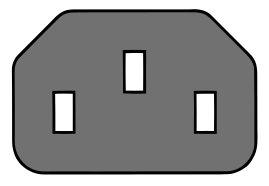 |
| Power cables (redundant power inlets, if available) |
1 | Scope: EPAS WORKER Connector type: C13/C14 Connector layout: |
| Power cables (redundant power inlets, if available) |
2 | Scope: EPAS AGENT Connector type: C13/C14 Connector layout: |
| Ethernet cable | 1 | Scope: EPAS MASTER to customer network Type: RJ45 Ethernet Cat 5/6/7 The network port should be enabled and ready for use when the system is powered on. |
| Ethernet cable | 1 | Scope: EPAS AGENT to customer network Type: RJ45 Ethernet Cat 5/6/7 The network port should be enabled and ready for use when the system is powered on. |
| Ethernet cable | 1 | Scope: EPAS MASTER to EPAS WORKER Type: RJ45 Ethernet Cat 5/6/7 The current section addresses the physical requirements for the EPAS deployment, specifically related to installation of the physical component and other pre-requisites for the datacenter installation. |
Physical installation
This section provides information on installing the EPAS chassis into a rack unit, using the provided rail installation kit. The instructions may differ due to the type of rack in the customer facility.
Each EPAS unit comes with two sets of rails:
- Inner rails, pre-attached to the device chassis, which require no assembly or intervention
- Outer rails, which are shipped with the system, in the box. Each outer rail is split into two separate sections and must be assembled before mounting into the rack
The steps are:
- Identify the left and right outer rails by examining the ends, which bend outward. Match the left front outer rail with the left rear outer rail and the same for the right rails.
- Align the round post in the rear rail (B) with the round hole at the end of the slot in the front rail (A), and slide the front section into the rear section.
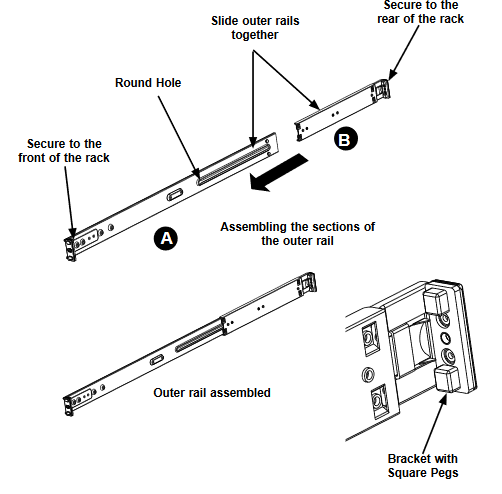
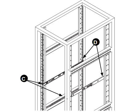
- Align the square pegs on the front end of the rail with the square holes on the front of the rack (C). Push the rail into the rack until the quick release bracket snaps into place, securing the rail to the rack. Keep the rail horizontal.
- Adjust the rail to reach just past the full depth of your rack.
- Align the square pegs on the rear end of the rail to the holes on the rack (D) and push the rail into the rack until the quick release bracket snaps into place, securing the rail to the rack.
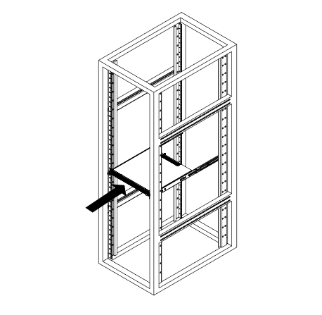
- Repeat the procedure for the other outer rail assembly.
- Align the chassis rails with the front of the rack rails.
- Slide the chassis rails into the rack rails, keeping the pressure even on both sides. The spring latch engages when the chassis is part way in. Push the server completely into the rack.
- Insert and tighten the thumbscrews that hold the front of the server to the rack.
Cabling and power-on
After the physical installation steps have been performed, the EPAS systems can be powered on. The steps are:
- Identify the cables mentioned in the Prerequisites section and connect them to the corresponding datacenter facilities (customer power units/PDUs and network switches).
- Identify the corresponding ports on the EPAS hardware, by inspecting the Specifications » Hardware Overview section and connect the cables to the corresponding ports (power supply unit(s) and network adapters).
- For systems with PSU status LEDs, the lights should indicate presence of power.
- Proceed by pressing shortly the Power Button to boot the hardware components.
- Confirm power-on by inspecting the Status LEDs or, acoustically, from fan spin-off procedure.