Hardware Specifications
This section describes the different hardware specifications for the revisions presented in the previous section.
Dimensions and weight
| Width (in mm) |
Height (in mm) |
Depth (in mm) |
Weight (in kg) |
|
|---|---|---|---|---|
| MASTER 1.0.1A | 437 | 43 | 503 | 15 |
| WORKER 1.0.1A | 437 | 43 | 716 | 15 |
| WORKER 1.0.4A | 437 | 178 | 737 | 45 |
| WORKER 1.0.8A | 437 | 43 | 716 | 15 |
| WORKER 1.0.8B | 437 | 43 | 716 | 15 |
| AGENT 0.0.2B | 439 | 43 | 368 | 10 |
| AGENT 1.0.1A | 437 | 43 | 429 | 12 |
| AGENT 1.0.8A | 437 | 43 | 503 | 14 |
Rack specifications
All models are built for standard full depth 19" rack enclosures.
| Rack space | Rack space (incl. extra space) |
Power | |
|---|---|---|---|
| MASTER 1.0.1A | 1U | 1U | 2x 100-240V/6-3A |
| WORKER 1.0.1A | 1U | 1U | 100-140V/14.7-10.5A 180-240V/10.5-8.0A |
| WORKER 1.0.4A | 4U | 5U | 4x 100-120V/12.5-9.5A 4x 200-240V/11.8-9.8A |
| WORKER 1.0.8A | 1U | 1U | 100-140V/14.7-10.5A 180-240V/10.5-8.0A |
| WORKER 1.0.8B | 1U | 1U | 100-140V/14.7-10.5A 180-240V/10.5-8.0A |
| AGENT 0.0.2B | 1U | 1U | 100-240V/6.3-3.24A |
| AGENT 1.0.1A | 1U | 1U | 2x 100-240V/6-3A |
| AGENT 1.0.8A | 1U | 1U | 2x 100-240V/6-3A |
Hardware overview
This section describes the different hardware ports and components, to be used during the installation procedure.
Note
Although different EPAS hardware models differ in number of ports or number of power supplies, the generic port architecture and positioning is the same, for each hardware type (MASTER, WORKER, AGENT). Therefore, one subsection of each type is present.
MASTER 1.0.1A
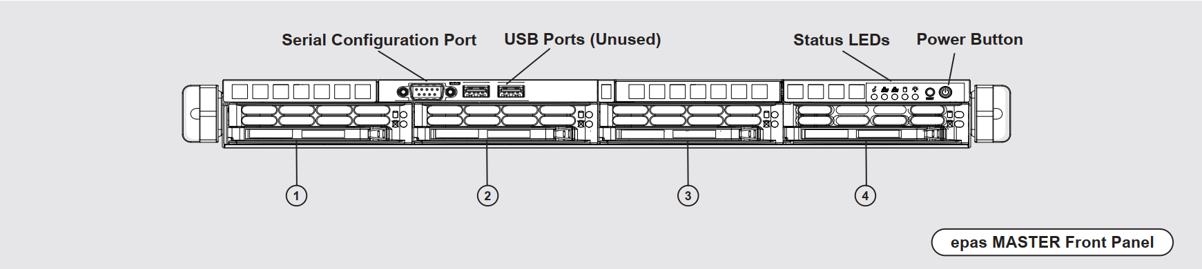
Front Panel
| Label | Component | Description |
|---|---|---|
| N/A | Serial Configuration Port | A standard RS232 communication interface, to be used during the initial configuration or hardware installation step (IP address configuration). |
| N/A | USB Ports (Unused) | USB interfaces, not used for productive purposes. |
| N/A | Status LEDs | Status indicators for network, disk and power state. |
| N/A | Power Button | Used for powering on the EPAS system. Short press for standard power off (if the machine is responsive). Long press (5s) for forced power off (if the machine is non-responsive). |
| 1 | Internal Drive | This hard drive slot contains the private, encrypted, main EPAS disk. Used for the firmware, internal database and private dictionaries.Can not be removed |
| 2 | Dictionary Drive | This hard drive slot contains the public dictionary disk. This disk contains the default set of dictionaries supplied by the vendor, as well as any generated dictionary lists by the customer. Can be removed, or mounted in external systems |
| 3 | Backup Drive | This hard drive slot contains the local EPAS backups (which are performed by EPAS administrators in the backup menu). While the filesystem of the disk is not encrypted, the backup contents are encrypted with a randomly allocated key, which is wrapped to the system TPM and (optionally) the vendor's rewrapping key. Can be removed, or mounted in external systems |
| 4 | Unused Slot | This slot is empty and can be used for further EPAS product expansion disks. |
Warning
Removing the Internal Drive can result in potential physical damage, as the hardware assembly and cabling procedure can, in some cases, block the drive slot removal. DO NOT REMOVE without prior confirmation from the product vendor.
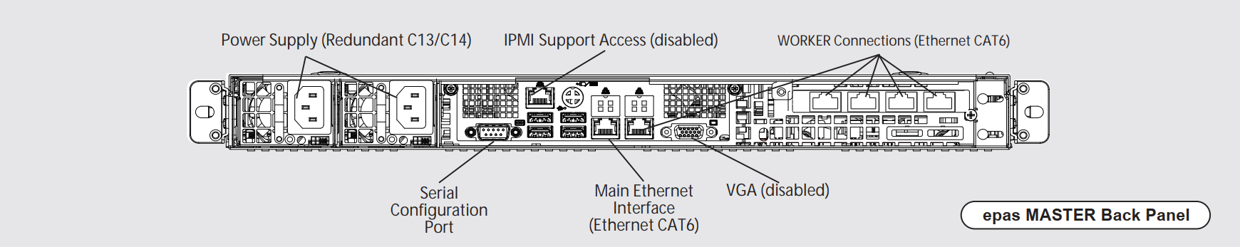
Back Panel
| Component | Description |
|---|---|
| Power Supply | Indicates the power supply connector location. For systems with dual (or multiple) power supplies, it is recommended to use redundant PSUs |
| IPMI Support Access | This Ethernet port is disabled for all productive deployments and is unused/not connected |
| WORKER Connections | One motherboard Ethernet CAT6 port, and a switch containing 5 or more Ethernet CAT6 ports to be used for DIRECT connection to WORKER modules. |
| Serial Configuration Port | A standard RS232 communication interface, to be used during the initial configuration or hardware installation step (IP address configuration). |
| Main Ethernet Interface | Ethernet CAT6 connection to the customer network. EPAS MASTER has a single customer connection through this port. |
| VGA | This video/display port is disabled after the initial boot procedure. Not used for productive purposes, should not be connected. |
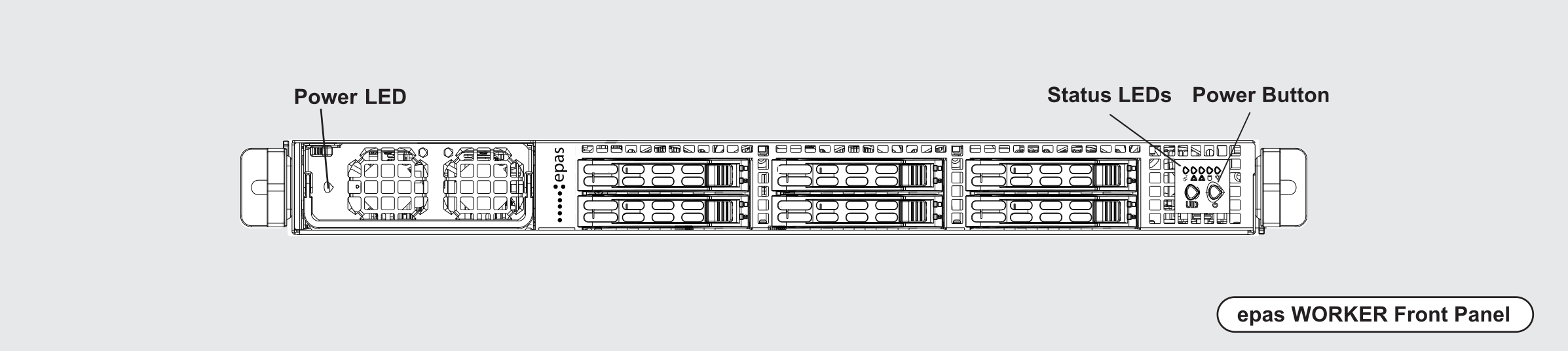
WORKER 1.0.1A
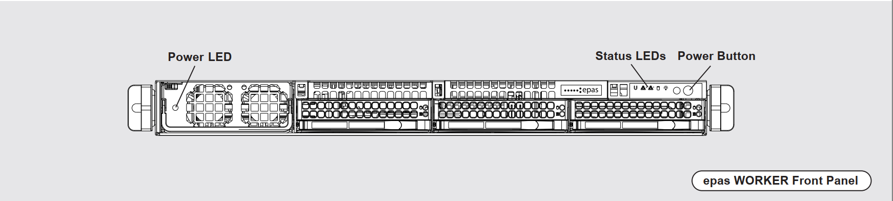
Front Panel
| Label | Component | Description |
|---|---|---|
| N/A | PSU LED | Status indicators for the power supply unit. Indicator should be green when WORKER system is online. |
| N/A | Status LEDs | Status indicators for network, disk and power state. |
| N/A | Power Button | Used for powering on the EPAS system. Short press for standard power off (if the machine is responsive). Long press (5s) for forced power off (if the machine is non-responsive). |
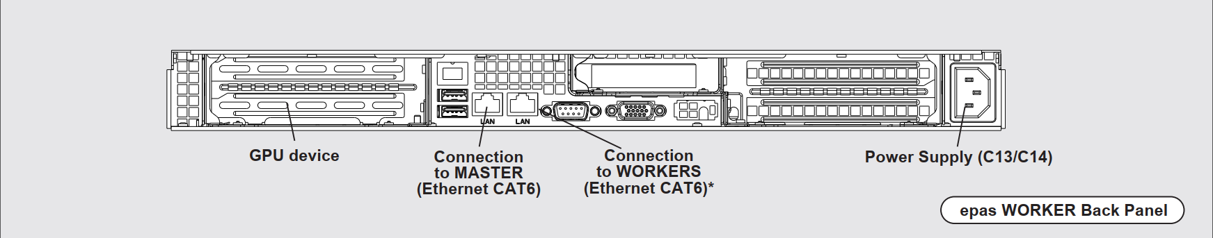
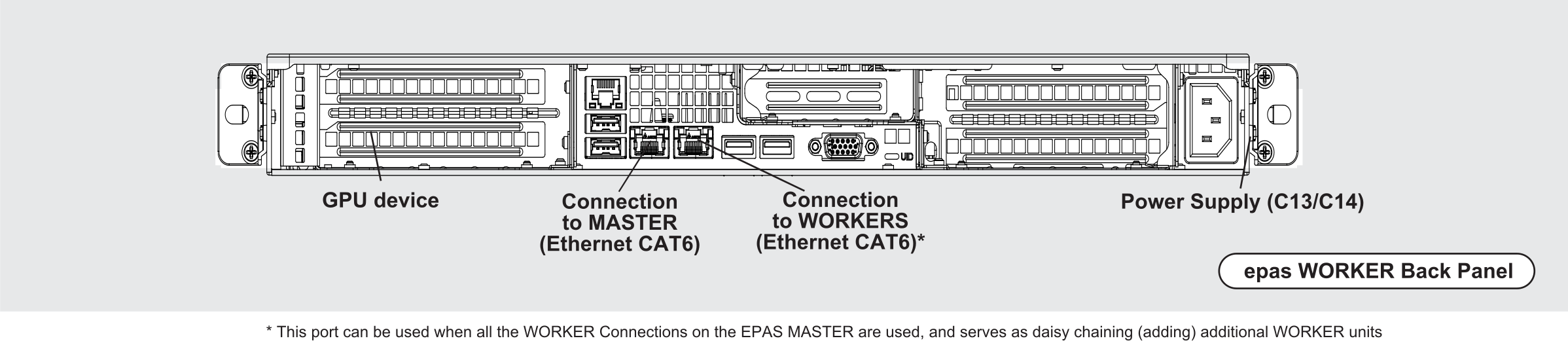
Back Panel
| Component | Description |
|---|---|
| GPU Device | The back panel slot is used for housing the GPU module, used for password recovery. The slot should not be blocked by any extenders, cables or third party power units, as it is used for air exhaust. |
| Connection to MASTER | DIRECT Ethernet CAT6 connection to the EPAS MASTER. |
| Connection to WORKERS | DIRECT Ethernet CAT6 connection to other EPAS WORKER systems, which are not connected to the EPAS MASTER. This port can be used when all the WORKER Connections on the MASTER are used, and serves as daisy chaining (adding) additional WORKER units. |
| Power Supply | Indicates the power supply connector location. For systems with dual (or multiple) power supplies, it is recommended to use redundant PSUs |
WORKER 1.0.4A
Front Panel
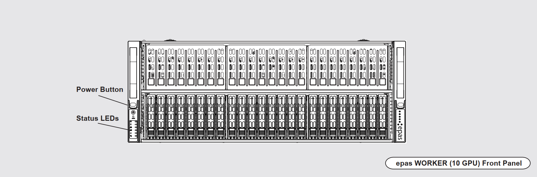
| Label | Component | Description |
|---|---|---|
| N/A | Status LEDs | Status indicators for network, disk and power state. |
| N/A | Power Button | Used for powering on the EPAS system. Short press for standard power off (if the machine is responsive). Long press (5s) for forced power off (if the machine is non-responsive). |
Back Panel
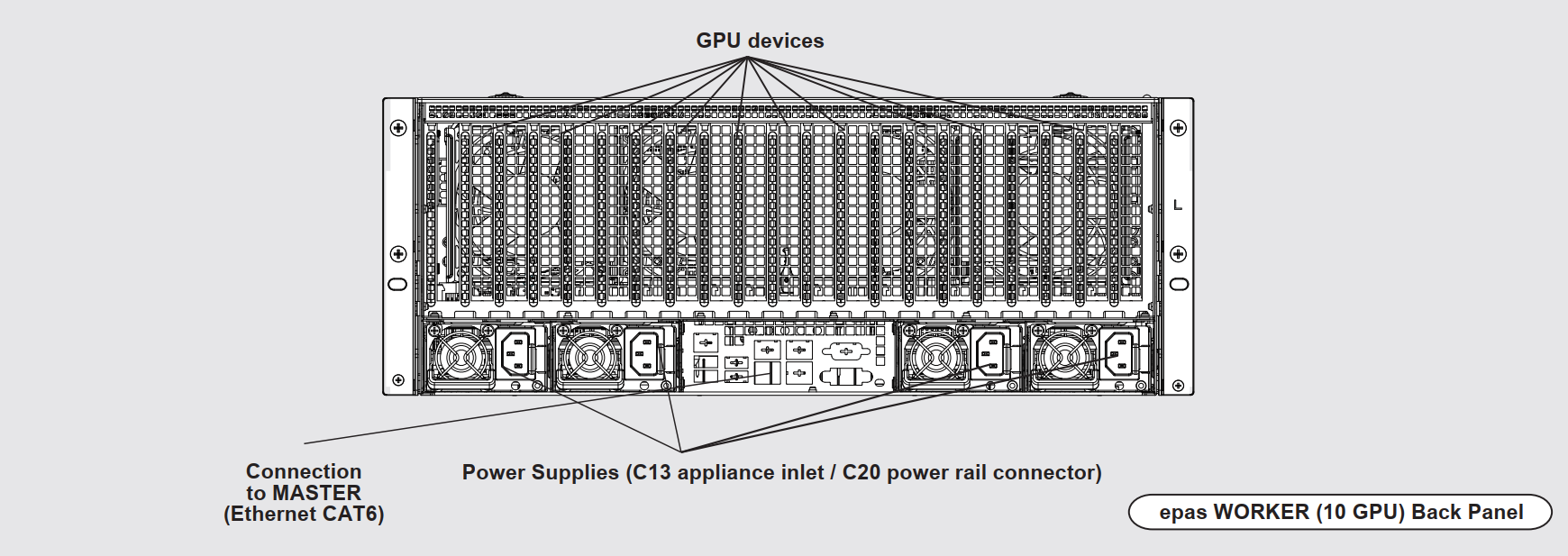
| Component | Description |
|---|---|
| GPU Devices | The back panel slot is used for housing the GPU modules, used for password recovery. The slot should not be blocked by any extenders, cables or third party power units, as it is used for air exhaust. |
| Connection to MASTER | DIRECT Ethernet CAT6 connection to the EPAS MASTER. |
| Power Supply | Indicates the power supply connector location. For systems with dual (or multiple) power supplies, it is recommended to use redundant PSUs. The inlet types are C13, while the power rail connector for the inlets should be C20 |
WORKER 1.0.8A
Front Panel
| Label | Component | Description |
|---|---|---|
| N/A | PSU LED | Status indicators for the power supply unit. Indicator should be green when WORKER system is online. |
| N/A | Status LEDs | Status indicators for network, disk and power state. |
| N/A | Power Button | Used for powering on the EPAS system. Short press for standard power off (if the machine is responsive). Long press (5s) for forced power off (if the machine is non-responsive). |
Back Panel
| Component | Description |
|---|---|
| GPU Device | The back panel slot is used for housing the GPU module, used for password recovery. The slot should not be blocked by any extenders, cables or third party power units, as it is used for air exhaust. |
| Connection to MASTER | DIRECT Ethernet CAT6 connection to the EPAS MASTER. |
| Connection to WORKERS | DIRECT Ethernet CAT6 connection to other EPAS WORKER systems, which are not connected to the EPAS MASTER. This port can be used when all the WORKER Connections on the MASTER are used, and serves as daisy chaining (adding) additional WORKER units. |
| Power Supply | Indicates the power supply connector location. For systems with dual (or multiple) power supplies, it is recommended to use redundant PSUs |
WORKER 1.0.8B
Front Panel
| Label | Component | Description |
|---|---|---|
| N/A | PSU LED | Status indicators for the power supply unit. Indicator should be green when WORKER system is online. |
| N/A | Status LEDs | Status indicators for network, disk and power state. |
| N/A | Power Button | Used for powering on the EPAS system. Short press for standard power off (if the machine is responsive). Long press (5s) for forced power off (if the machine is non-responsive). |
Back Panel
| Component | Description |
|---|---|
| GPU Device | The back panel slot is used for housing the GPU module, used for password recovery. The slot should not be blocked by any extenders, cables or third party power units, as it is used for air exhaust. |
| Connection to MASTER | DIRECT Ethernet CAT6 connection to the EPAS MASTER. |
| Connection to WORKERS | DIRECT Ethernet CAT6 connection to other EPAS WORKER systems, which are not connected to the EPAS MASTER. This port can be used when all the WORKER Connections on the MASTER are used, and serves as daisy chaining (adding) additional WORKER units. |
| Power Supply | Indicates the power supply connector location. For systems with dual (or multiple) power supplies, it is recommended to use redundant PSUs |
AGENT 0.0.2B
Front Panel
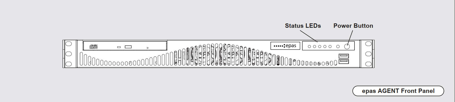
| Label | Component | Description |
|---|---|---|
| N/A | Status LEDs | Status indicators for network, disk and power state. |
| N/A | Power Button | Used for powering on the EPAS system. Short press for standard power off (if the machine is responsive). Long press (5s) for forced power off (if the machine is non-responsive). |
Back Panel
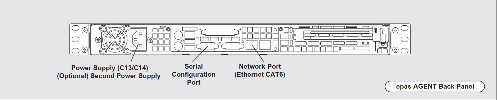
| Component | Description |
|---|---|
| Power Supply | Indicates the power supply connector location. |
| Serial Configuration Port | A standard RS232 communication interface, to be used during the initial configuration or hardware installation step (IP address configuration). |
| Main Ethernet Interface | Ethernet CAT6 connection to the customer network. EPAS AGENT has a single customer connection through this port. |
AGENT 1.0.1A
Front Panel
| Label | Component | Description |
|---|---|---|
| N/A | Status LEDs | Status indicators for network, disk and power state. |
| N/A | Power Button | Used for powering on the EPAS system. Short press for standard power off (if the machine is responsive). Long press (5s) for forced power off (if the machine is non-responsive). |
Back Panel
| Component | Description |
|---|---|
| Power Supplies | Indicates the power supply connector location. For systems with dual (or multiple) power supplies, it is recommended to use redundant PSUs |
| Serial Configuration Port | A standard RS232 communication interface, to be used during the initial configuration or hardware installation step (IP address configuration). |
| Main Ethernet Interface | Ethernet CAT6 connection to the customer network. EPAS AGENT has a single customer connection through this port. |
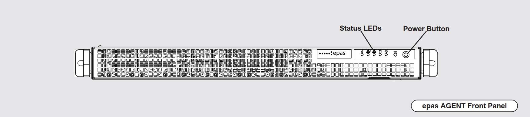
AGENT 1.0.8A
Front Panel
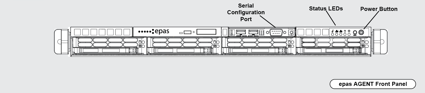
| Label | Component | Description |
|---|---|---|
| N/A | Serial Configuration Port | A standard RS232 communication interface, to be used during the initial configuration or hardware installation step (IP address configuration). |
| N/A | Status LEDs | Status indicators for network, disk and power state. |
| N/A | Power Button | Used for powering on the EPAS system. Short press for standard power off (if the machine is responsive). Long press (5s) for forced power off (if the machine is non-responsive). |
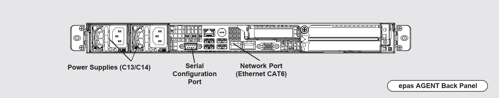
Back Panel
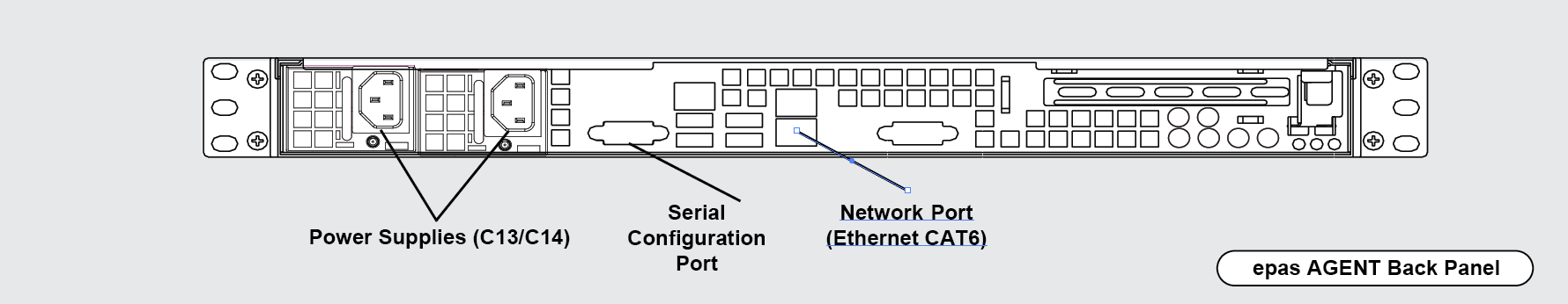
| Component | Description |
|---|---|
| Power Supplies | Indicates the power supply connector location. For systems with dual (or multiple) power supplies, it is recommended to use redundant PSUs |
| Serial Configuration Port | A standard RS232 communication interface, to be used during the initial configuration or hardware installation step (IP address configuration). |
| Main Ethernet Interface | Ethernet CAT6 connection to the customer network. EPAS AGENT has a single customer connection through this port. |